Remote Trigger with Arduino

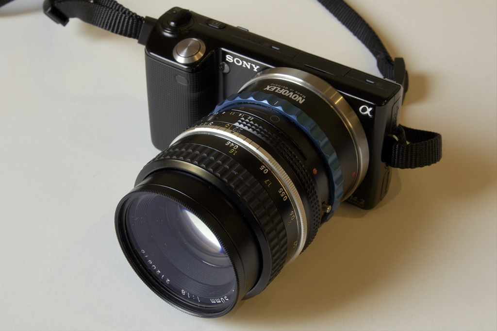
One problem with the Sony NEX 5 camara series is the lack of a decent remote shutter mode. You are able to switch it to IR mode and use the IR remote control to take a picture. However you can’t combine any of the other available trigger modes like bracketing or high speed trigger with the IR remote control. I wanted to change this and started this project described here: The ultimate remote trigger for the Sony NEX 5 using a servo and an arduino board. I called this project The Ultimate Trigger V1.

Creative Commons License The Ultimate Trigger V1 is licensed under a Creative Commons Attribution-ShareAlike 3.0 Unported License.

The remote control has four different possibilities for taking a picture:

  • Software – Via code running on a host computer sending commands to the COM port where the arduino is attached
  • Arduino – Via code running on the arduino itself (not implemented at the moment)
  • IR remote – Via an arbitrary IR remote control
  • Cable – Via an attached remote release cable

The following image shows the finished breadboard version. You see the arduino board in blue on the left above the yellow 9V battery. Between the arduino board and the battery is the attached wireless remote receiver. In the middle you find the white breadboard with the necessary electronics. On the NEX you see the servo attached via a cable strap and a rubber band. On the right you see the wireless remote transmitter and the IR remote transmitter.

Ultimate Trigger V1 - Overview

This image shows the breadboard in detail: On the breadboard you find from top to bottom:

  1. The attached servo (a JR type model with brown, red and orange cables)
  2. The attached wireless receiver. This could also be any other type of Minolta, Konica-Minolta or Sony remote cable release. The receiver is a third party RF wireless type.
  3. The IR receiver able to receive most types of consumer IR remote controls.
  4. Three status LEDs with the necessary series resistors.
Ultimate Trigger V1 - Details

This image shows the breadboard design in detail. It has been made with Fritzing.

Ultimate Trigger V1 - Breadboard

This image shows the schematics of the electronics (also made with Fritzing).

Ultimate Trigger V1 - Schematic

The following code for the arduino sketch makes use of two libraries: Servo (included in the arduino IDE) and IRremote!

/*
 * Ultimate Trigger V1
 * by Markus Matern aka PanoTwin Markus
 * 
 * Release: 20120107
 * 
 * This code is licensed under the Creative Commons Attribution-ShareAlike 3.0 Unported License.
 * To view a copy of this license, visit http://creativecommons.org/licenses/by-sa/3.0/
 * or send a letter to:
 * Creative Commons, 171 Second Street, Suite 300, San Francisco, California, 94105, USA.
 */
 
#include <Servo.h>
#include <IRremote.h>
 
// Servo configuration
const int servoPin = 11;
const int minimumAngle = 0;
const int maximumAngle = 179;
const int zeroAngle = 100;
const int wakeUpAngle = 107;
const int shootAngle = 110;
Servo myservo;
 
// Wireless remote configuration
const int triggerWhite = 10;
const int triggerBlue = 9;
int whiteVal = LOW;
int blueVal = LOW;
 
// IR receiver configuration
int RECV_PIN = 8;
IRrecv irrecv(RECV_PIN);
decode_results results;
 
// Diagonstic configuration
const int ledStatus = 7;
const int ledTrigger = 6;
const int ledError = 5;
 
void setup() {
  // Diagnostic setup
  pinMode(ledStatus, OUTPUT);
  digitalWrite(ledStatus, HIGH);
  pinMode(ledTrigger, OUTPUT);
  digitalWrite(ledTrigger, LOW);
  pinMode(ledError, OUTPUT);
  digitalWrite(ledError, LOW);
 
  // Servo setup
  myservo.attach(servoPin);
  myservo.write(zeroAngle);
 
  // Wireless setup
  pinMode(triggerWhite, INPUT);
  // make sure the input pin is not undefined
  digitalWrite(triggerWhite, HIGH);
  pinMode(triggerBlue, INPUT);
  // make sure the input pin is not undefined
  digitalWrite(triggerBlue, HIGH);
 
  // IR receiver setup
  irrecv.enableIRIn(); // Start the receiver
 
  // Serial setup
  Serial.begin(9600);
}
 
void shoot(){
  StatusTrigger(1);
  myservo.write(wakeUpAngle);
  delay(1000);
  myservo.write(shootAngle);
  delay(1000);
  myservo.write(zeroAngle);
  StatusTrigger(0);
  delay(1000);
}
 
void wakeUp(){
  StatusTrigger(1);
  myservo.write(wakeUpAngle);
  delay(1000);
  myservo.write(zeroAngle);
  StatusTrigger(0);
  delay(1000);
}
 
void minAngle(){
  StatusTrigger(1);
  myservo.write(minimumAngle);
  delay(1000);
  myservo.write(zeroAngle);
  delay(1000);
  StatusTrigger(0);
}
 
void maxAngle(){
  StatusTrigger(1);
  myservo.write(maximumAngle);
  delay(1000);
  myservo.write(zeroAngle);
  delay(1000);
  StatusTrigger(0);
}
 
void Blink(int blinkLed,
           int milliseconds,
           int blinkCount)
{
  for(int i = 0; i < blinkCount; i++)   {
      Status(blinkLed, 1);
      delay(milliseconds/blinkCount/2);
      Status(blinkLed, 0);
      delay(milliseconds/blinkCount/2);
    }
  }
  void BlinkBeforeTrigger(int milliseconds) {
    Blink(ledTrigger, milliseconds, 3);
  }
  void StatusTrigger(int newStatus) {
    Status(ledTrigger, newStatus);
  }
  void StatusError(int newStatus) {
    Status(ledError, newStatus);
  }
  void Status(int pin, int newStatus) {
    if(newStatus){
      digitalWrite(pin, HIGH);
    } else {
      digitalWrite(pin, LOW);
    }
  }
  void loop() {
    // remote control via serial communication
    if (Serial.available() > 0) {
    int b = Serial.read();
    switch(b) {
      case 't':
        shoot();
        break;
      case 'w':
        wakeUp();
        break;
      case '0':
        minAngle();
        break;
      case '8':
        maxAngle();
        break;
      default:
        Blink(ledError, 600, 3);
        break;
    }
    Serial.flush();
  } else if (irrecv.decode(&results)) {
    switch(results.value)
    {
      // Sony Shutter (2 Sec)
      case 0xECB8F:
        StatusTrigger(1);
        Blink(ledTrigger, 2000, 4);
      // Note: No break here!
      // fall through to shoot!
      // Sony Shutter
      case 0xB4B8F:
        shoot();
        break;
      case 0:
        break;
      default:
        StatusError(1);
        Serial.println(results.value, HEX);
        Blink(ledError, 600, 3);
        StatusError(0);
        break;
    }
    // Receive the next value
    irrecv.resume();
  } else {
    // Check the wireless remote trigger
    int newWhiteVal = digitalRead(triggerWhite);
    int newBlueVal = digitalRead(triggerBlue);
 
    if (newWhiteVal != whiteVal) {
      if (newWhiteVal == HIGH) {
        //Serial.println("White High");
        myservo.write(zeroAngle);
        StatusTrigger(0);
      } else {
        //Serial.println("White Low");
        StatusTrigger(1);
        StatusError(0);
        myservo.write(wakeUpAngle);
      }
      whiteVal = newWhiteVal;
    }
    if (newBlueVal != blueVal) {
      if (newBlueVal == HIGH) {
        //Serial.println("Blue High");
        StatusError(0);
      } else {
        //Serial.println("Blue Low");
        myservo.write(shootAngle);
        StatusTrigger(1);
        StatusError(1);
      }
      blueVal = newBlueVal;
    }
  }
}

Nikon Nikkor 20mm f/2.8 AI-s and Novoflex NEX/NIK

The Novoflex NEX/NIK adapter makes it possible to mount Nikon lenses on the Sony NEX camera line. Read more about the lens here.

Nikon Nikkor 50mm f/1.8 AI and Novoflex NEX/NIK

The Novoflex NEX/NIK adapter makes it possible to mount Nikon lenses on the Sony NEX camera line. Read more about the lens here or here. On the Novoflex homepage you find an adapter finder here.

The Nikon 50mm f/1.8 AI is a manual lens. The Novoflex NEX/NIK adapter is also only a manual adapter. However this is not a problem with the Sony NEX-5. You just have to be aware of some things.

  1. Make sure you enable the shooting without a lens: Menu → Setup → Release w/o lens → Enable
  2. Before you continue make sure you have Firmware ≥ Ver. 04 installed! Check this using Menu → Setup → Version. When you have an older version installed download the latest version from the Sony support site here.
  3. Enable the MF Assist function using Menu → Setup → MF Assist → 2 Sec
    You can choose between No Limit — 2 Sec — 5 Sec.
  4. Enable the Peaking Level using Menu → Setup → Peaking Level → Mid
    You can choose between Low — Mid — High.
  5. Choose your Peaking Color using Menu → Setup → Peaking Color→ Red
    You can choose between YellowRed — White.

Switch your camera to A- Mode (aperture priority) and use the MF Assist button to get a perfectly sharp picture even when shooting the lens wide open with f/1.8!

Reprojecting equirectangular images for a printed presentation – Scripts

During our talk about “Reprojecting equirectangular images for a printed presentation” in Palmela and Vienna we presented two scripts you can use to reproject images using a so called Droste – effect. See some examples in these posts.

Here is a short overview over the software we used, you can consider this as the required runtime environment for the scripts:

Software Version Platform
The Gimp 2.6.11 Windows; Linux; Mac
Mathmap Plugin for The Gimp 1.5.3 Windows; Linux; Mac
Adobe Pixel Bender Toolkit 2.5.449694 Windows; Mac

One of these is a script for the Gimp’s Mathmap Plugin. The other one is a script for the Pixel Bender Toolkit. The problem with the original two scripts is, that the parameters they use have different names and they are implemented differently! E.g. sizes are pixel sizes in one script and percentages of the image size in the other script. I wanted to be able to use the same parameters in both environments. So I started to bring the scripts back together.

The main motivation for this was to be able to work on large files. The Pixel Bender stand alone version has a size limitation depending on your graphics card. This may be a maximum of 2048×2048 pixels or like in my case 4096×4096 pixels. When you want to process larger images you have to switch to The Gimp. These size limitations do not apply there! The Mathmap rendering on the other hand is really slow compared to the Pixel Bender. This is because Mathmap renders the final image and the preview on a single core of your CPU. The Pixel Bender toolkit renders both on the GPU!

This table shows links to the original scripts (Mathmap V10 and Pixel Bender V1.1) and the modified versions with exchangable parameters (Mathmap V11 and Pixel Bender V2).

Script (Download link) Version Link
Droste for Mathmap (Original) V10
Droste for Mathmap (PixelBender compatible Version) V11 This article
Droste for PixelBender (Original) V1.1 Homepage
Droste for PixelBender (Mathmap compatible version) V2 This article

See two screenshots of some sample settings using Mathmap and Pixel Bender and the original and transformed image:

For an example workflow on how to generate a Droste spiral effect from a 360° panoramic (or equirectangular) image image read this post.

Acknowledegements go to the following persons, who started the first versions of the scripts: Mathmap: breic, Josh Sommers; Pixel Bender: Tom Beddard
You find further information about the Math behind the Droste effect here and here.

Reprojecting equirectangular images for a printed presentation

We held a talk at the Palmela International Panoramic Photography Festival: Reprojecting equirectangular images for a printed presentation and also at the PanoTools Meeting 2011 in Vienna.

You can find the video recording of the talk in Palmela here.

The talk showcased the benefits of reprojecting equirectangular panoramas for static presentations. We have presented “simple” reprojections and also two–step reprojections using a series of transformations. An overview was given about the different available tools to reproject panoramas. Numerous “real life” examples were shown, including the original equirectangular image and possible reprojections.

The presented reprojections were based on scripts working with two different tools PixelBender (stand alone or plugin for PhotoShop) and the MathMap plugin for The Gimp.

Download the Droste reprojecting script for PixelBender here: PixelBender Droste Reprojection Script

Download the Droste reprojecting script for Mathmap here: Mathmap Droste Reprojection Script

Reprojected Three Green Stripes (Making Of)

In this article I try to explain the steps, that were necessary to get the result I presented in the previous post. The consecutive steps are explained below and a preview of the result is shown twice. The first one is the original image, the second one a coloured chequered artificial image.

  1. I decided to make a panorama from inside a tripartite pillar. The exact pillar is shown on the image below.
    Three Green Stripes Panorama Location
  2. I used my usual workflow and took three images for each direction. Furthermore I made a zenith and nadir shot. I used the Sigma 8mm F4 fisheye lens on a Sony Alpha 700 and shot RAW images. Postprocessing was made with Bibble 5 Pro.
    Three Green Stripes Raw Images
  3. I stitched the images into an equirectangular image using PTGui Pro. The final panorama was 8000×4000 pixels in size.
    Three Green Stripes EquirectangularColoured Chequered Equirectangular
  4. This equirectangular image was reprojected using again PTGui Pro using a stereographic projection with a field of view of 333° and a pitch angle of 90°. The result is the following image. The original image had a size of 5550×5550 pixel.
    Three Green Strips Cloverleaf ProjectionColoured Chequered Cloverleaf Projection
  5. For  a Droste spiral effect I had in mind you need a somehow circular masked image. I’ve chosen to mask the “leafes” and scale the image down to 4000×4000 pixel. The result was the following image :
    Three Green Stripes Cloverleaf Projection MaskedColoured Chequered Cloverleaf Projection Masked
  6. The last step in the transformation process was again a reprojection applying the Droste effect using the Pixel Bender Toolkit. You find the Pixel Bender filter and an introduction into the Droste effect in this post. The basic parameters for the Droste filter were: strandMirror: yes; transparentInside: yes; transparentOutside: yes; twist: yes; periodicity: 3; strands: 2. I played around with the rest of the parameters until I was satisfied with the result.
    Three Green Stripes Droste ReprojectionColoured Chequered Droste Spiral

Multirow Spherical Panorama made with the Sony NEX-5

Some weeks ago a question came up, whether it is possible to stitch a panorama from so called sweep panoramas made with the Sony NEX-5. The short answer is: NO. You can read the detailed answers in my two recent posts: #1 and #2.

Here is now the result with the same camera and lens: A Sony NEX-5 with the pancake 16mm lens. I mounted the camera on a tripod and shot a multirow panorama with three rows, each row using eight portrait shots. I used a custom panorama head that I set up quickly for the new camera/lens combination (it has not been aligned perfectly for the NPP).

I set the image quality for shooting to RAW. The resulting images were processed using Bibble 5 Pro. Almost the only processing done with Bibble was correcting the CA of the lens. Further processing like correcting lens vignetting and adjusting the a, b and c parameters for the lens was done with PTGui Pro.


Fountain in Schwabing

Geotag Icon Show on map
QR Code Business Card